Progress on the Solar Tracker

Well I made progress on the solar tracker. All 3D printing done. Mechanical assembly done.

Assembled Tracker on Tripod

Next, I need to solder pins onto the ESP32 and wire it up and figure out where the two stepper driver boards go.

closeup of the electronics

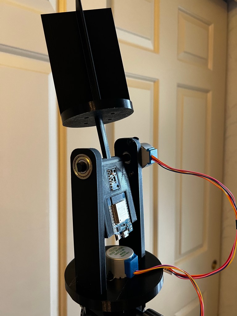
As you can see the electronics fit into recesses in the tilting platform. the smaller module is the magnetometer /accelerometer.

In practice, the azimuth axis needs to spin about 370 degrees while the code does compass calibration. Since the wiring between the esp32 and the stepper move together on the axis that wiring won’t be a problem, but the usb cable feeding power and serial will have to have enough slack for the full rotation.

On the alt axis, the wiring to the stepper only needs enough slack for 90 degrees of tilt. the software will prevent over rotation. However, again, the usb cable might be a problem as you can see there is not a lot of clearance for the connector between it and the stepper.

Once the software is finalized, io to the tracker will be over wifi, so instead of a usb cable, I should be able to attach batteries and a voltage regulator, so then only two power lines will attach to the esp32, making cableing easier.

Update on the Solar Tracker/Logger

Well I did choose to go with an ESP32, I’ve already written the code, which I’ll tweak once everything is together. And I did get the first draft of the 3D printed parts:

Which consists of a:
1. Base — that fits on an Arca tripod mount (I borrowed the arca part from another person’s design. If I make this project public I’ll let people know where to get the arca mount that they can add to my adaptor to make the base.
2. Rotating Base — this is the azimuth axis.. it swivels on a single skate board bearing, direct driven by a stepper.
3. A Sensor Head — This holds 4 photo resistors, and has baffles that will cast shadows on them if the sun is not aligned. So basically if any pair of sensors reads the same voltage, they are both in full sun and so aimed in that dimension at the sun. as the sun moves, a shadow will be cast on one of them, the voltages will differ in the pair and the code steps the appropriate motor to get the voltages equal again.
4. A tilt platform — This is the alt axis. This platform rotates on 2 skateboard bearings, one end is direct driven by a stepper. The sensor head attaches to this. Also there are recesses to put the ESP32 and magnetometer/accelerometer.

What the code does is sense the voltages on the circuits the sensors are connected to, step the motors to equalize the voltages — this aims the tilting platform in alt and az at the sun, then reads the mag/accel sensor for heading and tilt. It will run a web server and allow a client to get the latest: alt, az and time those readings were taken. (I synchronize the ESP32’s clock by NTP to my NTP server in the house.) A raspberry pi will act as the client, and log sun positions, and yes, perform the necessary adjustment to go from magnetic heading to true heading.

What’s missing? Well right now there is no place for the stepper drivers to sit. So they’ll just hang out. Also it probably needs to have the tilt platform balanced, it seems like it will be weighted towards the sensor head. Testing will tell if the stepper has enough torque so that this is not a problem. if it is a problem I’ll glue some weight onto the electronics platform.