We sometimes forget and leave the kitchen faucet running. I looked into automatic faucets, but they’re expensive and would need a plumber to install. So, like with other things around the house, I started thinking about how I could tie something into our home automation system to warn us when the faucet is on.
On Amazon I found sensors you can install inline with your plumbing. They detect water flow and connect over Wi-Fi or Zigbee so they can integrate with home automation — but they cost over $200 and still require a plumber. Not much better than buying an expensive faucet!
Then I had an idea. Some clamp-on water alarms detect flow just by the sound of running water. Why couldn’t I do the same thing with a microphone and a small computer?
Well, it turns out I can.
First, I experimented on my laptop, which already has a mic. With some help from AI, I “directed” the creation of a Python program that listens through the mic and breaks the sound into all its frequency bands (using an FFT — Fast Fourier Transform). I added a simple graph to show the sound spectrum, and visually discovered where running water has the most energy. With that, we were able to build software logic that detects when the faucet is on or off — and it worked!
Next, I needed something that could stay by the sink. I used a spare Raspberry Pi 4 and a $4 USB mic from an old project, and got the same program running there. After a little tuning, it became a reliable running-water detector. From Python it’s easy to trigger events on my home automation system, so I created a rule: whenever the faucet alarm switch turns on, my living-room speaker announces “Faucet On!”
It works perfectly — and it cost me nothing but a bit of time and curiosity. I saved hundreds of dollars and learned something new in the process.
Like a lot of computery hardwary people, I have been buying and setting up Raspberry PI 4’s for various tasks around the house.
For instance I replaced an aging Mac Mini house file server with a Raspberry PI 4 and a 2 disk software Raid1. And one of my 3D printers is controlled by a Raspberry PI 4 with OctoPi installed on it.
But also last summer I set up a Pi 4 system, on a battery and solar panel, out in the garden to do weather satellite image receving over an SDR radio.
Before the pandemic, PI 4’s were relatively cheap, and they run Raspberry PI OS (a linux veriant) or even Ubuntu. So you get a PI board, a case, heat sinks, fan and power supply and you have a low cost computer that runs a real operating system.
Except when the chip shortage came, PI 4’s were very expensive just for the board, and are only now coming down in price, probably mostly because they introduced the PI 5. Well lets look at the economics of it… A PI5 board alone is selling for about $100 on Amazon. To use it as a general purpose computer, you need to add a case, a power supply and active cooling (PI 4 got by with just a fan, the 5 seems to need more elaborate cooling) .. so the power supply costs about $20, and the case plus cooling costs about $25… You have to add a micro SD card to this, pick a size, so we’re looking at about $150ish for a PI computer, and that’s without a monitor, keyboard and mouse — in some applications I run headless anyways.
I was about to put in an order for one, because lately I’ve been designing and building my own microcontroller boards, and frankly, I risk, due to my inexperience, blowing out a USB port on my expensive laptop if I plug it in and have something wrong in the wiring. So I figured, hey, buy a cheap Raspberry PI system and you only risk blowing out a port on a $100 computer board.
Well If all I want to do is run the PI as a terminal emulator to my boards, that’s fine, and probably I could get PlatformIO running on it and I can do Arduino sketch development right on the PI… but as I have advanced in things, I see I’m leaving Arduino land and I want to run more serious IDEs from chip makers themselves. For instance Microchip’s MPLAB X, which will run on linux, but not on a PI.
That got me looking for what very cheap PC could I buy instead of a PI, and I found, on Amazon, a $155 Intel N95 based computer. It’s about as long as a PI enclosure width wise, and depth is about twice a PI enclosure. so still a tiny single board computer, that has all the IO and video ports a PI has, plus USB-C, and like a real computer, it comes in a case, with a power supply and whatever cooling it needs, there are notable advantages over a PI 5. First it is an x86-64 machine, comes with Windows 11 installed and of course will run Linux if you want. Second, it has a real 512 gig SSD, as opposed to running off a micro sd card like a PI, and has 16 gigs of ram installed (upgradable), wheras the PI 5 seems to max out at 8 Gigs.
So price wise, there’s no reason now to buy a Raspberry PI system, and performance wise, well I’ve set mine up, installed the IDE I will be using, and found for sure it blows away a PI 4 performance wise, (I don’t know about vs a PI 5, I don’t have one).
The only reason I thought a PI could still have an advantage is that you can run a PI off a battery… But this N95 machine has a DC input jack on it, and the wall wart that comes with it is only 12v 3a. So hey… no problem running that off a 12 volt battery.
As I mentioned in a previous post, I built my own minimum ATMega 2560 board to help with my Z80 single board computer project. Here is a video update on where I’ve gone as far as programming microcontroller boards.
Back last spring and summer I was doing photography, and especially astrophotography. Well I eventually decided it was effecting my sleep cycle because in the summer you have to get up in the midnight to like 4am range for good dark skies. So I said “Wait till winter. It will be dark after dinner.”
But in the winter it is too cold! So instead of astrophotography I’ve been doing Ham Radio — which got to be a problem when I ran out of things to say on the radio, and so now I’m back on to electronics.
So I dusted of my Z80 computer design work, and redesigned it as a spiffy single board computer. One conundrum I had in last year’s design was that I did not want to set aside space for an EPROM, since I have no idea yet what sort of OS I was going to put on it, I had no idea how to size it. Many designs on the web just give it 16k or 32k of EPROM… which is huge.
But I stumbled upon a nifty chip… it’s a 128k NVRAM… what it is is low power, but pretty fast static ram with a built in lithium backup battery… So now that’s the best of both worlds… It will act like a ROM in that it will retain it’s memory when powered off, but I don’t have to know at hardware design time how much memory to set aside for the OS..
So I had panel switches in my design so I could manually “toggle” in a bootstrap program, to then pull in the OS off of something like an SD card, but instead what I decided to do was just make another board to program the NVRAM with a basic “ROM monitor”.
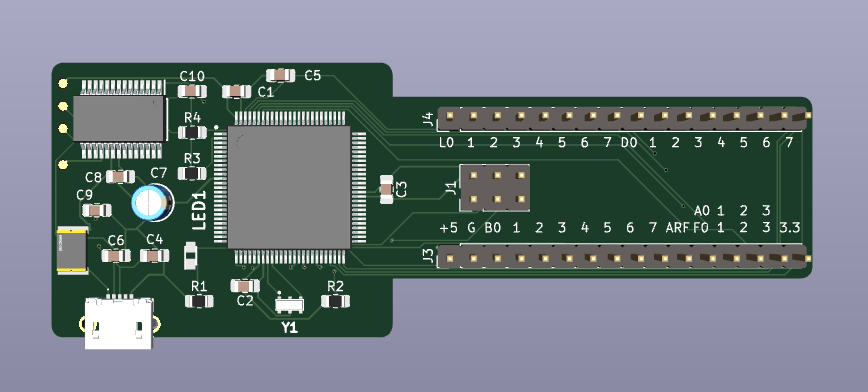
So I designed and, wow, already built a tiny Arduino compatible Atmega 2560 board to be the controller in the programmer. It was my first real SMD component board, and my first use of a cheap reflow oven I bought quite a while ago, but hadn’t used yet. The board is very basic, all it has on it is the 2560, a USB-UART chip, a 16mhz resonator. So very basic and also I brought out 16 pins, +5v, 3.3v, Gnd, 28 GPIO pins, and AREF (4 of the GPIO pins are also ADC inputs). Well I made the board key shaped so that the header pins are on an outboard portion of the board so that it is breadboard friendly — the 2560 is a big chip and would not normally fit on a board that fits on a breadboard.
So 28 GPIO pins is exactly what I need to program the NVRAM chip… that’s 17 address lines, 8 bidirectional data lines, and 3 control lines (~CE, ~WE, ~OE).
Once built and debugged, I wrote a first version of the ROM monitor, but this one compiled for the 2560 and targeting the NVRAM chip. I can do only basic things… Examine and deposit individual memory cells, and, wow, I can also do Kermit file transfers for over the serial port file receives… So now I realized I don’t need panel switches on the Z80 board since it will have a Z80 compiled version of the monitor, which will also be able to pull in executables via Kermit.
And with about a days’s work, it worked! I did spend an additional earlier day trying to implement YMODEM, but found that protocol is not very well documented, and since Kermit is very well documented, and simple, I ultimately went with Kermit.
I built a version of the NVRAM programmer on a breadboard. It did work, but is just a mess of wires, and so it would be hard to remove and put back the NVRAM, or even the 2560 board– which I assume I’ll do as I develop the final monitor for the Z80…
You can see in this pic that the the 2560 board would normally cover all the pins on the breadboard, thus the key shape to allow room to plug wires onto the breadboard… the footprint is the same as a .1 by .6 pitch 32 pin DIP socket.
So I designed a PCB board for the task that I can plug the 2560 in and it has a ZIF socket for the NVRAM chip. Note those 3 resistors hanging out up at the top of the breadboard… Those are pull-ups on the 3 control lines… Since I am re-using the 3 SPI pins as GPIO pins, and the 2560 uses a combination of RESET and SPI to program itself, it’s pretty critical to not have anything active on the SPI pins during system RESET. Well the SPI pins landed as 3 of the data pins for the NVRAM chip… also one of the data GPIO is also for the onboard LED….. so the first time I powered it up I had a light show as the NVRAM chip had floating control lines it was doing strange things on it’s data lines, and the 2560 was struggling to figure out what sort of program was coming in to the chip. Adding pull-ups was all that was needed, the NVRAM chip now comes up with it’s data lines tri-stated.
OUCH! I actually made the same mistake when I sent the board out to have the PCBs made. I forgot to put the pull-ups into the schematic… But it’s all good now… except I’ll have 3 spare PCB’s for my mistake that I can hack pull-ups onto if I need them. All I need to do is wait about a week for the boards to come in…
So I got all the pieces together since my last post about weather satellite images. The hardware update is I got a very nice antenna:
Click the photo to see on Amazon.com
That alone improved reception, by eliminating a lot of noise. Also added an LNA:
Click the photo to see on Amazon.com
That’s placed right at the feed point of the antenna, it amplifies the raw signal, filters it for just the 137mhz band, and amplifies it again. (note, if you intend it for all weather operation, you’ll have to do something to weatherize this unit)
Those two things gave me the most clear satellite images I’ve gotten yet, and more importantly, it pulls the signal in from lower satellite elevations, so I get more of the pass, meaning I get more of an image in the north/south direction. You can see with this photo, I get almost from the arctic down to a good chunk of Florida on a good pass:
Now it was time to make this work in the garden for real. So I have a back corner garden, it has the biggest view of the sky in my yard, and gets a good amount of sun for the solar panel… So I’ve had a setup of a 25 watt solar panel, a 21 amp hour gel battery, and a charge controller that I’ve used to put other experiments out in the garden… however those experiments were done with a small circuit board with a relatively cheap ESP32 on it… That draws maybe 400ma… and I was able to run that experiment (A magnetic field logger) pretty far into the winter before it quit.
Now the the Raspberry PI 4 can draw up to 3 amps, which is significantly more than the panel/battery combo was designed for… but I gave it a try. I had it attached in such a way that the charge controller would cut power to the PI if the battery dropped below 10.5 volts — to save the battery… It’s a deep cycle battery, but it should not be drawn down to zero.
For waterproofing… the battery and charge controller are in a plastic battery box that has 2 downward facing vents on it. But there’s a problem… on a night when the dew is strong, it gets moisture condensing in the box… this is not good. It really needs a fan for airflow.. but I’m not sure if I can afford the power…
So since I don’t want my pie to get damp, I bought a waterproof electrical box… put the PI and the SDR radio in it and all looked happy. Then a sunny day came, and wow great for the solar panel, but not so great that the waterproof box has no where to dissipate heat… running compute intensive stuff with the radio and LNA running caused the PI to detect an overheat situation. Also at the same time it drained the battery down and the charge controller shut the whole show down…
So I tried again… Now I have a task that runs once a minute on the PI. it uses “vcgencmd” to get the throttle state of the PI… if it detects a persistent under-voltage, or over heat it kills all the satellite tasks and hopes for things to cool down before the next pass.
Ok so another very hot day came along, and at least the task shutdown worked, and the pi began to cool off. But not fast enough for me… So I moved the whole thing into the battery box again, and now the task is…figure out how to get heat out of a sealed plastic box.
I’ve done calculations and the panel should be able to more than keep up with the PI, meaning it should result in a net charging up of the battery… The problem is.. when a processor runs hot it draws more current than normal. And it’s probably why when the first heat situation hit, and was runaway, it drained the battery down below the threshold.
One more thing… I have an RTL_SDR dongle… if you turn the bias tee on to power the LNA.. well it stays on even when you’re not using the radio.. It stays on until you explicitly turn it off… That never happens in Raspberry-NOAA-V2.. so I inserted a command to shut the bias tee down between passes. This saves 300ma which is significant.
So now also on order is a “Witty PI” — which is a daughter board you attach to the PI.. it does nifty power management, like,, shut the pi down on low voltage, hight temperature, and or on a schedule… That’s exactly what I need… I can ditch the charge controller low voltage system and use the Witty PI’s version… if voltage goes to low it will do a graceful shutdown of the pi, and wait till voltage charges back up again, if the temp goes too high, it will do the same,… and for extra power saving, I can shut the pi down on a schedule, since the satellites have a consistent morning and evening schedule…there’s a good 8 hours of no passes, that I can basically shut down and draw zero power during.
By the way.. the pi itself has no real way to shut down and come back on again on it’s own because it has no real time clock. also when you halt a PI 4, it still consumes 300ma on it’s own just to sit and do nothing. The Witty PI will bring that down to an absolute zero for the pi because it controls the PI power source. The Witty PI itself draws less than 10ma when idle.
The whole image covered the entire east coast USA. I cropped the usable piece out. The raw image looks like white clouds on a gray background. Processing software inserts land and water coloration and state borders and precipitation probability.
Ok, Here is more info about receiving weather satellite images…
What you need (for NOAA APT and Meteor LRPT sats): 1. a radio that can receive in the area of 137 to 138 MHZ 2. a suitable antenna, tuned for that band 3. some way to capture the audio 4. some software that converts the captured audio to an image.
Oh and you’ll need to somehow get satellite tracking information
But in my case specifically I’ve gotten and done this: 1. got an RTL-SDR Blog V3 sdr radio (already had one for short wave listening). This is a USB device, you hook an antenna to it, and hook it to a usb port, you can use the suite of software in the rtl_sdr linux package to do basic radio listenning 2. Well I’ve been in the antenna hacking stage, right now I have it hooked up to a dipole antenna of mine that just happens to have low SWR in the area of 137.5MHZ. But ever hating fussing with antenna construction, I ordered what’s called a V-Dipole built just for NOAA weather sat reception. So a V-Dipole is just a dipole but the two elements in this case are set at an angle of 120 degrees to each other, rather than having them in a straight line. By doing this it basically get omnidirectional reception and also reception from UP, where the sats are. The actual antenna to use for this is a helical antenna built for the weather sat band, Unfortunately I cant’t find clear instructions online to build, and I see no one selling one, I did see at a legit ham radio store site, that you could pay $300 for a built one for another band. Uhm… No. 3. and 4. To capture the audio and process it I am using Raspberry-NOAA-V2, findable on Github. basically you devote a raspberry pi 2 or greater to have a fresh OS install, and install that software, It does the full job of tracking sats, and listening at the right time, and converts the audio to sat images with various “enhancements”.
NOAA sats, NOAA 15, 18 and 19, are in a polar orbit, sun synchronous , meaning they fly pole to pole, with a period of about 90 minutes, and they keep themselves aligned with the sun, so that their images always have the same lighting on the day side. They don’t have a normal camera in them, they have more or less a single line Earth scanner in them… so as they fly they are scanning a line of the earth perpendicular to their path, and they put out about 2 scan lines a second. The signal is analog, AM modulated on a 2400hz carrier, the whole shebang is FM modulated somewhere in the 137mhz band, a different channel for each sat. The Meteor sat is a Russian sat that uses a digital encoding, but it’s the same basic scanning idea, just a different scan line encoding.
You don’t really need to know all that, you use software to decode the signals, and generally you can expect NOAA images to be like old time TV, sometimes a clear signal, sometimes snowy. And the Meteor, being digital, will be clear, but with black lines where the decoder failed to hear a decent signal.
Well, Raspberry NOAA V2 (RN2), is a great package that just handles everything for you to track, record and decode the 3 NOAA sats and a Meteor sat. I’m running mine on a headless RPi 4, with minimal OS (no GUI). RN2 runs a web server on the pi so you can check schedules and look at captured images.
Well we have to talk about the Meteor M2 saga.. It seems that Meteor M2, was giving great results — looking back at other people’s posts and videos about it, but it has failed… and it’s replacement ? Failed. So now we’re up to the newly launched Meteor N2-3. Support for that sat in RN2 is in beta development. I took a peek at that code, and found that, yes, once it is released I can expect amazing sat photographs from it.
And we should talk about the realities of antennas and Raspberry PIs….
I have played with radios since I was in grade school. Always putting a lot of energy into the question — why is my reception so bad? I have played with antennas and long ago came to the conclusion that they are magic, and a kind of magic I can’t grasp. Sure there are formulas, and calculators, and simulators all for designing the perfect antenna, but when it comes down to it, you never have the perfect antenna, and you never have the perfect antenna installation.
So these few days have been spent fussing with antennas. And as I said.. I ordered one, and hope it does it’s magic, but in the mean time, this above is the best image I got so far, and it was done with a hacked together v-dipole from an old TV rabbit ears, at ground level (Some say go as high as possible, some say no.. it needs to be between .4 and .6 meters off the ground.)
Mind you… as far as antennas and SDR and RPi’s go… the PI itself is a noise source. USB is a noise source… so I have two chokes on the USB cable to the SDR dongle, I have a choke on the power going in to the PI, and I have everything stretched out so the SDR dongle is as far from the PI as possible, and the antenna is as far as possible away.
Earlier today, I used my 40M OCF Dipole, (installed in my garage):
So you can see my motivation… that image says I have the potential to get images from the gulf of mexico up to way north in canada…
My next steps: Once the actual antenna comes in, install it properly. Also I have a 137mhz band pass filter on order. Also have a much better radio on order. Ultimately this is all going into a waterproof box in my garden. I had put together a 12v battery, a solar panel and a charge controller, for a past experiment… Now it will be re-purposed as the beginning of my garden weather station.
Not that there will ever be a clear night in my area again.. I’ve continued to refine the barn door tracker.
So as I said in my last post.. the tracker will home itself now upon power up or reset. The process takes about a minute — mostly because the stepper won’t go more than 10rpm, and in the final homing stage I go 2rpm so I approach the home click slowly.
Well other than looking at the gears to see what direction they are spinning, which seems difficult if it’s dark out, also considering everything is in black plastic, I decided to put some audio feedback in the system. Now it beeps out beep codes telling me what it’s up to.
To do that I bought one of these, Fielect Active Buzzer Modules:
Click the image if you’d like to check it out on Amazon. If you decide to buy one too, and use that link it will help support this blog.
Now it came with no instructions, just labels on the pins, vcc, i/o, gnd. and some printing on the bottom saying it has a low trigger. Oh, and the buzzer itself has a sticky label on it that says “Remove after washing”… uhm… washing? At any rate, it seemed logical to remove the sticker since it covers up the sound hole of the buzzer.
So my assumption is, if I put a logic low on the i/o pin it will beep, and a logic 1, it should be silent. and I connected up power to 5 volts.. hey because I have a pin header where I can get 5 volts, and not where I can get 3.3volts.
Well that’s not gonna work… the ESP32 logic level 1 is 3.3 volts. Apparently that’s not high enough to convince the transistor on the unit to see logic level 1. So no matter what digital output, LOW, or HIGH I put out, it just constantly beeps. And it beeps loudly.
OK, so I’m lazy, I could unplug all the leads to the ESP32 for the tracker, solder on a pin header where I can get 3.3 volts to supply the beeper, and re-wire everything. What a mess.
So it was time for some hacking. Normally in Arduino land, you say “pinMode(PIN, OUTPUT). Then digitalWrite(PIN, HIGH) puts out 3.3 volts), and digitalWrite(PIN, LOW) puts out 0 volts.
But if you say pinMode(PIN, OUTPUT_OPEN_DRAIN) it does something else… digitalWrite(PIN, HIGH) floats the pin (in other words like no connection), and digitalWrite(PIN, LOW) grounds the pin.
Now that works. I can turn the beep on and off. But yes.. it is a total hack, that avoids taking things apart and getting out the soldering iron.
I did verify, using a different ESP32 I have which has 3.3v on a pin header, and the beeper works as expected. Configuring it as just OUTPUT, and sending out a LOW turns makes it beep, sending out a HIGH turns off the beep.
I’ve seen people online try to use Arduino tone() with these things, and yes that will make it put out different frequency tones, but an active buzzer is not supposed to be used that way.
Here is some code demonstrating both switching the beeper on and of — for a little blip of time, and then using tone.
To start off, this will be a type of review of a product I bought on Amazon, I have to state that I have no connection at all with the seller, or manufacturer, my only connection is that I’ve included an Amazon affiliate link in this post, so if you buy one from that link I’d get some monetary benefit. I bought one with my own money.
Overall, I like it very much. But I have a couple negatives.
The positives is that it is quite easy to set up. You will have to solder on the supplied 5 pin header in order to connect to it via the UART, and to get access to the PPS signal. The UART connection is just like any other GPS module, and I was able to substitute it in to my Raspberry PI time server, in place of the original module (Which I was borrowing from one of my ham radios), very easily.
It takes a few minutes to get the first fix (and by the way, it needs to be near a window). but after that it gets a fix within seconds, since it has an onboard battery to keep it’s memory of the last satellites it heard.
I like it because it is really small as you can see in the picture, and came with a patch antenna, and it is inexpensive at $10.99 (at time of writing this).
One more plus is it must not draw much power. My Raspberry PI 2 is pretty marginal on available power for peripherals.. but I’ve checked and got no power drops or throttling while using it.
Now the down sides. Though it has a micro-usb connector on it, and if you look at the traces on the board it is wired to provide data on USB, I could not figure out how to get USB going with it and my Raspberry PI. A downside being there are no instructions, and also no web articles about how to make that work. Why no web articles? Well probably because everyone is using the UART connection, not USB.
The patch antenna was a little tricky to install. Probably mostly because of my bad close vision, but with magnification, it became clear how the connector connects.
Also twice now, upon power up, yes it gets a fix, yes it gets accurate time (My main purpose for it), but no, it has a completely wrong location. What I’ve found is just power cycling it, and it will get a good location. I can’t explain it, but it’s possible mine is not getting a good signal all the time, I have it in a sun room, that has 3 walls of all windows. I haven’t dug in to why it is doing this, but I do know it has nothing to do with antenna placement, since once I power cycled it without moving it at all, and the problem went away.
I definitely will buy it again for any other time keeping applications, and I may buy one just to play with.
Click the image to check it out on Amazon, if you buy through that link it will helps support this blog.
So I’ve built a star tracker, and with a 40mm lens and only using an iPhone compass and bubble level to polar align it, I was able to get 30 second photos without star trails.
But I need to push the envelope. I want longer exposures and now have an external intervalometer to do that, and I also want to be able to use my 18-200mm lens at 200mm.
Initial tests with the 18-200mm lens, again with iPhone alignment, said — I get star trails.. So I set it up level in the house, and ran it for a while with the camera on and the iPhone level on it, making casual readings with a stop watch, and for sure, the lens was probably too heavy for that little stepper and an 8mm pitch lead screw.
So I got a 4mm pitch lead screw, it should be able to lift twice as much right? Got up at some insane time of night and took photos at 200mm and got star trails.
Ok, so there are at least two things that cause this… ok 3 things. One is that the longer the lens the more inaccuracies of the whole setup will show and cause star trails. Two is that if the polar alignment is out… you get star trails, three if the system clock of the microcontroller is inaccurate, you get star trails.
So to get a lot more precise in looking for causes, I did this:
I set the tracker up level on a tripod in my house. I put a big X on white background registration mark at the pivot, and at the end of the arm that swings. And I made a 30fps HD video of it for about 16 minutes.
That’s the data collection, now for processing I loaded the movie file into blender and used object tracking to track those two marks for the 16 minutes of the video.
Then I played all day with blender… ok but really then I wrote a python script that transforms the swing arm tracker’s position so that the pivot position is the origin — for each frame and printed to a file the angle of rotation of the swing arm tracker about the pivot origin.
Now by subtracting the start angle from the end angle, I had the total degrees (Yes I work in degrees not radians 🙂 swung in 16 minutes… it should have been so close to 4 degrees it’s not funny. But it actually came out to 3.75 ish degrees which is 6% slow.
That and a bad polar alignment probably explains star trails… since the stars are rotating slightly faster than the camera. For short exposures, it might not be noticeable, but I want long exposures, and I believe I can do it with this tracker with a little work.
Let see, does this data imply that I “should” see star trails in a 60 second exposure… We can figure this out… Photo Pills will give the max exposure time for an untracked photo with a given camera and lens combination. For my camera and that lens it says the NPF rule for it says max exposure of .94 seconds before a noticeable star trail. Ok, so 6% of 60 seconds is 3.6 seconds.. so I should see star trails due to the difference between .94 and 3.6, and Yes I did. Also I also took exposures at 30 seconds – which are 1.8 seconds slow… again that’s greater than .94 seconds, and yes I saw trails.
So the barn door tracker is basically a sidereal clock. At the root of it is it’s dependence on an accurate system time, since the amount of turns per degree for the lead screw depends on how wide the hinge is already open… Unlike a tracker with a curved screw, this tracker has a straight screw so the steps per degree needs to be variable.
Well the system clock on the ESP32 is based on a quartz crystal and so that in itself is very accurate, but there are a plethora of other places inaccuracies come in. Like we’re dealing with physical things all manufactured to their individual tolerances… the screw is a 4mm pitch screw, but not exactly 4mm. The stepper has so many steps per revolution, and that should be accurate, but how accurate? The trigonometry used in the program to compute the number of steps at time T, depends on the dimensions of the tracker, The designer used the dimensions in the design files, but what I have is something printed on my printer… My printer prints things to pretty accurate dimensions, but accurate enough? How far of from ideal?
So you could go through the whole system looking for sources of inaccuracies… and try to refine things, but there is another approach….
So in 16 minutes I measured a 6% discrepancy in angle… (ooh.. there’s also inaccuracies in my measurements too), how consistent is that? Well looking at the star trails in a 1 minute exposure gives me nice clean looking trails… if there was any speeding up and slowing down cycle, or just changes in speed the thickness of the trails would not be nice and uniform.
So on the assumption that the system all together is slow, what I can do is make a longer measurement. Set it up again, and video it for like 2 hours (that max I’d want to use the thing without resetting it)… and run that through my Blender code. From that I should be able to make a time dependent correction factor to the number of steps needed at any given point in time to bring it into correct timing.
It’s worth a try — alternatively I say — well this was fun— and spend thousands on a manufactured equatorial mount, and a guide scope… Thousands. Of. Dollars.
Well i have seemingly dozens of usb cables sitting around with every conceivable combinations of end connectors and lengths. I need them all, but not all at once. I’ve tried stuffing them in a drawer, but then they tangle and make it hard to find the one i need at the moment.
i can’t be the only one swimming in usb cables, how can i organize them?