Reviving My Kodak Portrait 3D Printer with Raspberry Pi Solutions

Years ago I bought a Kodak Portrait 3D printer. It is a great printer, very solid, mechanically excellent, with two nozzles, and it can print ABS. The problem is, very shortly after I bought the printer it became orphaned by the company that built it. The whole system was mainly cloud based. You used a custom version of Cura that uploaded G-code files to the cloud, then you logged into their website to initiate printing and could watch the job using its built-in webcam. That worked for a while until it didn’t. Their version of Cura is now hopelessly out of date.

So step number one was to figure out how to get a modern Cura to slice for the machine. It wasn’t easy, but I eventually wrote a script that Cura applies after slicing to patch up the G-code.

The next problem was that the only way to print a job was to put it onto a USB stick and print from the stick. That is very inconvenient. You have to walk over to the printer, grab the stick, go back to your computer, put the stick in, write the file, eject the stick, pull it out, and walk over to the printer again.

I wanted something that acted like a USB drive but could take files over Wi-Fi. I couldn’t find one, so I made one using a Raspberry Pi Zero 2 W. Several Raspberry Pi models have what is called Gadget Mode. Instead of acting as a general-purpose computer with USB host ports, you can flip it around so the USB port behaves like a device when plugged into some other computer’s host port. There are several device types it can emulate: a network adapter, a USB MIDI device, a keyboard or mouse, a game controller, and a USB drive.

By putting a Zero into gadget mode as a USB drive, I created a small volume on the Zero’s system SD card to hold the contents of this virtual USB stick. Any files placed on that volume show up on the host computer as if they were on an inserted USB drive. There is some trickiness involved, because the host computer (in this case the 3D printer’s internal Raspberry Pi controller) only scans the directory on insertion. So I wrote a script that detaches the gadget mode drive, mounts the volume on the Zero, writes a file to it, unmounts, and reattaches the gadget mode drive. From the 3D printer’s point of view, the USB stick was removed and reinserted, so it sees the new file.

Next, I used Samba and a directory-watcher Python script that calls the file-transfer script whenever a file is dropped into an inbox directory.

Now, from Cura, I can use “Save to File”, select the Pi’s network share, drop the file in, and as if by magic, the file shows up on my printer’s UI when I walk over to start the print.

Note: I had help from AI to write the code and to suggest edits to this blog post.

Barn Door Tracker, upgrade and measurement.

I spent a couple days fussing with the barn door tracker.

I built it according to the design, and off the bat it worked very well with my 40mm lens.

But… I wanted to use a much heavier lens, and a more demanding one.. 18-200mm at 200mm.

Ok so the first night out with it I was using probably a bad set up to do the polar alignment. The night with the 40mm lens all I did was use my iPhone compass and bubble level to line it up.. and it performed well. The night I tried the 200mm lens I used version 1 of my polar finder scope setup.

I got star trails, but that was ok, because that night I unexpectedly photographed comet in the field of view while photographing Jupiter.

So this set me off on 2 paths. One to improve the polar alignment setup, and 2 to completely analyse all the sources of error in the barn door tracker as a system, to see if it just can’t do 200mm. I talked to the designer, Peter Qun and he said, yeah.. 200mm is pushing it too hard.. it’s designed for wide angle lenses.

So I went ahead anyways to see if I could squeeze error out of the system. And there are many sources.. the camera is heavy with such a long lens, and the thing is 3D printed, so there could be flexing and twisting.. The gears are 3d printed, so definitely not perfectly round, nor probably having the hub in the center –my printer is great, but realistically…

So I got this idea, put registration targets on the axel and at the end of the moving hinge, make a 16 minute video, and use Blender object tracking and some python code I wrote to read out angles every 30th of a second…

According to that it was running slow.. like 8% slow as far as angle… Then I learned that the stepper used has different versions, with different internal gear ratios… Peter’s code uses a steps per revolution figure that’s based on some people in arduino land taking steppers apart that weren’t meeting spec, and they found that rather than having a 64:1 gear reduction, it was like 63 point some awful fraction.. leading to about 2038 steps per revolution… Since I had to by 5 steppers in the package, I took one of mine apart, counted teeth and found that oops… my version really is 64:1… so I should be using 2048 steps per rev.

Well I updated the code and remeasured, and I got the error down to 3%. Since I had a lot of data, I tried to come up with an overall correction factor for angle, tried that and it did not help…

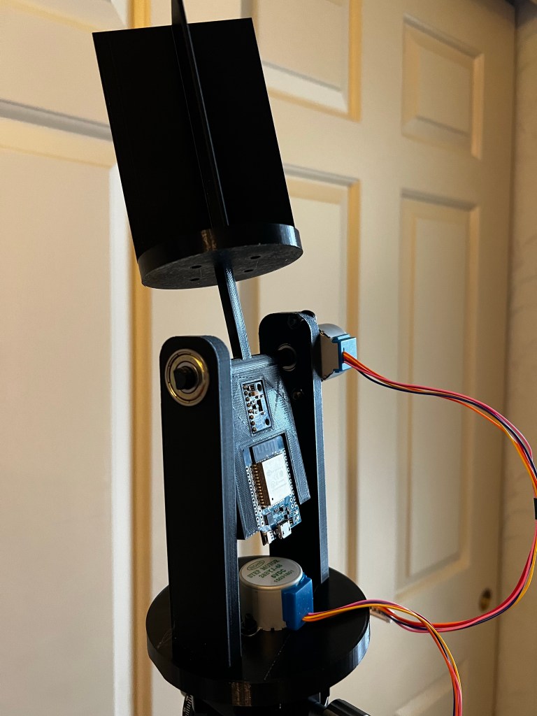
Being industrious I thought, hey… Why am I trying to make an open loop system be accurate? How about closing the loop by attaching an accelerometer module to the hinge, and read out the actual angle in real time.

Click the photo to check out the magnetometer/accelerometer I used from Amazon, buying it will also support this blog.

Oh.. Oh.. I learned a lot about accelerometer modules… They are totally noisy… But with a lot of filtering it looked like, if I set the tracker up level (not polar aligned) it did a reasonable job of stepping to the right angle at the right time, but no better really than the open loop version. Plus, though I had the math right so that the I could calculate pitch angle from the accelerometer data, even if I tipped the tracker.. I find out that at extreme angles, (such as 43.1, my latitude), the calculation for pitch angle is not reliable. Sources say, it’s only really accurate for small deviation from level.

So scrap the accelerometer, that I still have superglued to my tracker…

But this experience with angles and tilting and measuring, made me realize, that using Blender.. though it may be very accurate in object tracking, is very susceptible to the angle between my camera, and the tracker.. they’d have to be perfectly square to each other to read an accurate angle.. so scrap that idea.

So I resigned to just use it with the 40mm lens — why not? and decided to do a little upgrade.

The way it’s designed, you take apart part of the tracker, manually turn the lead screw to screw the hinge fully closed, and then bolt it down.. Which is fine, you use it for an hour or two, and maybe decide to reset the thing, and manually close it to set it up again… But ever looking to make life convenient I went about adding a micro switch to the end of the hinge. And I wrote code that homes the tracker upon startup or pressing the reset button.

Click on the photo above if you want to buy the same microswitches I did on Amazon, and support my blog at the same time.

Surprisingly — That much is very repeatable… Just like a 3d printer, the code checks to see if it is already homed, if so, move it up from home a bit.. then at a relatively high speed step it down seeking the home position, then move it up just a tad so it’s just off home, and now step it down slowly to finally find a good home spot. Now there is a bit of a risk to this procedure… considering the microswitch holder and it’s pusher are 3d printed parts, if either of them break off in the processes, the tracker will probably self destruct as it crashes down never finding home. I could not think of a fail safe for this… The microswitch is normally open, you seek home until it just closes, a broken off switch will remain open.

but… Repeated measurements have it homing to the same spot within the accuracy of my ability to measure it with my calipers.

Next was to, forget Blender, and just let the system home, track for 4 minutes and stop.. allowing me to make measurements at the home position, and at the 4 minute mark, repeatedly. and also it displays how much it thought it moved the screw… After repeated measurements I get that I’m within .15mm of the desired displacement. I really can’t expect it to do any better than that. My caliper cost me about $20.. I could write a story about how measuring with a cheap digital caliper involves some guesswork.

In the final analysis… I’ll need a clear night, to do the real proof of how well it tracks.

Better Finder Scope Attachment for the Barn Door Tracker

Well, I’ve designed solid mounts so that I can mount my red dot finder to my camera and to the barn door tracker. What was going wrong in the first version is that there was a lot of wobble in the mounts. My fault, because my design for the shoe for the finder was inherently wobbly. The current attempt is based on a design on thingiverse.com, for basically a type of dovetail rail that the finder scope can attach too. The finder comes with it attached to an adapter to a Synta style shoe. And there’s absolutely no problem with that, except in my setup.. Here is a link if you want to buy one:

As you can see, the finder itself is clamped on to a pedestal that then attaches in to a shoe on a telescope… In my case that pedestal is so high, it limits the positions I can angle my camera to. So on thingiverse.com is a rail meant for my particular tracker that would accept a similar type of finder scope. Not exactly mine, but I used it as a starting point for my design. I ended up with a rail I can bolt to my tracker, has a low profile, and then I can slide the finder on and off and there is no wobble.

Rail for Barn Door Tracker

I also melded that rail design to a hot shoe mount, printed that, and that fits nice and snug into my camera hot shoe also without wobble.

Rail with Hot Shoe Mount

So the idea, as I think I explained in another blog entry, is that since the finder has alt/az thumbscrews on it that are normally used to align it to a telescope, I couldn’t count on those screws never turning. So without a reference of what 0 alt/0 az is, I saw no way to align it to my barn door tracker. There’s nothing on the tracker with which to sight the north star, to correct the aim of the finder. So my theory goes.. if my hot shoe is square and level to my camera lens axis, I can put the finder onto the camera, align it to the camera while sighting a star in the exact center of the camera frame and then adjust the thumb screws on the finder to line it up– conveniently my camera displays the square central focus spot through the viewfinder so I can really get exact. Once the finder is lined up, I can move it to the barn door tracker, and do a polar alignment.

So that’s step 1 in eliminating star trails. The tracker has to be well aligned to the pole. And I have to wait, looking like a week, for clear skies to try it.

Analysis of My Astra V2.1 Tracker’s timing

So I’ve built a star tracker, and with a 40mm lens and only using an iPhone compass and bubble level to polar align it, I was able to get 30 second photos without star trails.

But I need to push the envelope. I want longer exposures and now have an external intervalometer to do that, and I also want to be able to use my 18-200mm lens at 200mm.

Initial tests with the 18-200mm lens, again with iPhone alignment, said — I get star trails.. So I set it up level in the house, and ran it for a while with the camera on and the iPhone level on it, making casual readings with a stop watch, and for sure, the lens was probably too heavy for that little stepper and an 8mm pitch lead screw.

So I got a 4mm pitch lead screw, it should be able to lift twice as much right? Got up at some insane time of night and took photos at 200mm and got star trails.

Ok, so there are at least two things that cause this… ok 3 things. One is that the longer the lens the more inaccuracies of the whole setup will show and cause star trails. Two is that if the polar alignment is out… you get star trails, three if the system clock of the microcontroller is inaccurate, you get star trails.

So to get a lot more precise in looking for causes, I did this:

I set the tracker up level on a tripod in my house. I put a big X on white background registration mark at the pivot, and at the end of the arm that swings. And I made a 30fps HD video of it for about 16 minutes.

That’s the data collection, now for processing I loaded the movie file into blender and used object tracking to track those two marks for the 16 minutes of the video.

Then I played all day with blender… ok but really then I wrote a python script that transforms the swing arm tracker’s position so that the pivot position is the origin — for each frame and printed to a file the angle of rotation of the swing arm tracker about the pivot origin.

Now by subtracting the start angle from the end angle, I had the total degrees (Yes I work in degrees not radians 🙂 swung in 16 minutes… it should have been so close to 4 degrees it’s not funny. But it actually came out to 3.75 ish degrees which is 6% slow.

That and a bad polar alignment probably explains star trails… since the stars are rotating slightly faster than the camera. For short exposures, it might not be noticeable, but I want long exposures, and I believe I can do it with this tracker with a little work.

Let see, does this data imply that I “should” see star trails in a 60 second exposure… We can figure this out… Photo Pills will give the max exposure time for an untracked photo with a given camera and lens combination. For my camera and that lens it says the NPF rule for it says max exposure of .94 seconds before a noticeable star trail. Ok, so 6% of 60 seconds is 3.6 seconds.. so I should see star trails due to the difference between .94 and 3.6, and Yes I did. Also I also took exposures at 30 seconds – which are 1.8 seconds slow… again that’s greater than .94 seconds, and yes I saw trails.

So the barn door tracker is basically a sidereal clock. At the root of it is it’s dependence on an accurate system time, since the amount of turns per degree for the lead screw depends on how wide the hinge is already open… Unlike a tracker with a curved screw, this tracker has a straight screw so the steps per degree needs to be variable.

Well the system clock on the ESP32 is based on a quartz crystal and so that in itself is very accurate, but there are a plethora of other places inaccuracies come in. Like we’re dealing with physical things all manufactured to their individual tolerances… the screw is a 4mm pitch screw, but not exactly 4mm. The stepper has so many steps per revolution, and that should be accurate, but how accurate? The trigonometry used in the program to compute the number of steps at time T, depends on the dimensions of the tracker, The designer used the dimensions in the design files, but what I have is something printed on my printer… My printer prints things to pretty accurate dimensions, but accurate enough? How far of from ideal?

So you could go through the whole system looking for sources of inaccuracies… and try to refine things, but there is another approach….

So in 16 minutes I measured a 6% discrepancy in angle… (ooh.. there’s also inaccuracies in my measurements too), how consistent is that? Well looking at the star trails in a 1 minute exposure gives me nice clean looking trails… if there was any speeding up and slowing down cycle, or just changes in speed the thickness of the trails would not be nice and uniform.

So on the assumption that the system all together is slow, what I can do is make a longer measurement. Set it up again, and video it for like 2 hours (that max I’d want to use the thing without resetting it)… and run that through my Blender code. From that I should be able to make a time dependent correction factor to the number of steps needed at any given point in time to bring it into correct timing.

It’s worth a try — alternatively I say — well this was fun— and spend thousands on a manufactured equatorial mount, and a guide scope… Thousands. Of. Dollars.

I think I’ll try the hardware hacking approach.

Update on the failure to make a polar alignment scope

OK, so a few days back I posted about a couple clips I made so I could attach a red dot finder to both my camera and my Astra tracker.

See that entry for how I thought it should go, but how it actually went was I could not calibrate the scope. No matter how much I tried I got star trails even at 30 sec exposures, and the other night, just using an iPhone compass and level I was able to do 1 minute exposures with no trails.

So back to the drawing board. A person on thingiverse.com posted a shoe to attach the same red dot finder that I bought to the Astra. It has a lower profile and it looks like it will be far less wobbly than the one I made.

I do still need to adapt it to attach to my camera hot shoe, because I have no other way I can think about to calibrate the finder. It has 2 thumb screws one for fine adjust up/down and one for left/right.

To adjust to adjust those on the mount alone seems impossible.. You’d have to use the iphone to get a rough alignment, dial the scope to the north star, take a photo, see if it trails and then… what?… guess which way to move the mount and trial and error hunt for no trails?

No I figure if I attach it to the camera on a tripod, center a bright star in the camera view, which seems easy since there is a red box to center it in, dial in the finder, move the finder to the Astra mount, and well it should now be easy to point that at the north star.

It will take another sleepless, but clear, night to try again… I got up at 3:30am today, and clouds rolled in by 4:45, so also there’s not a lot of time to experiment in a cloudy region.

Progress on the Solar Tracker

Well I made progress on the solar tracker. All 3D printing done. Mechanical assembly done.

Assembled Tracker on Tripod

Next, I need to solder pins onto the ESP32 and wire it up and figure out where the two stepper driver boards go.

closeup of the electronics

As you can see the electronics fit into recesses in the tilting platform. the smaller module is the magnetometer /accelerometer.

In practice, the azimuth axis needs to spin about 370 degrees while the code does compass calibration. Since the wiring between the esp32 and the stepper move together on the axis that wiring won’t be a problem, but the usb cable feeding power and serial will have to have enough slack for the full rotation.

On the alt axis, the wiring to the stepper only needs enough slack for 90 degrees of tilt. the software will prevent over rotation. However, again, the usb cable might be a problem as you can see there is not a lot of clearance for the connector between it and the stepper.

Once the software is finalized, io to the tracker will be over wifi, so instead of a usb cable, I should be able to attach batteries and a voltage regulator, so then only two power lines will attach to the esp32, making cableing easier.

Update on the Solar Tracker/Logger

Well I did choose to go with an ESP32, I’ve already written the code, which I’ll tweak once everything is together. And I did get the first draft of the 3D printed parts:

Which consists of a:
1. Base — that fits on an Arca tripod mount (I borrowed the arca part from another person’s design. If I make this project public I’ll let people know where to get the arca mount that they can add to my adaptor to make the base.
2. Rotating Base — this is the azimuth axis.. it swivels on a single skate board bearing, direct driven by a stepper.
3. A Sensor Head — This holds 4 photo resistors, and has baffles that will cast shadows on them if the sun is not aligned. So basically if any pair of sensors reads the same voltage, they are both in full sun and so aimed in that dimension at the sun. as the sun moves, a shadow will be cast on one of them, the voltages will differ in the pair and the code steps the appropriate motor to get the voltages equal again.
4. A tilt platform — This is the alt axis. This platform rotates on 2 skateboard bearings, one end is direct driven by a stepper. The sensor head attaches to this. Also there are recesses to put the ESP32 and magnetometer/accelerometer.

What the code does is sense the voltages on the circuits the sensors are connected to, step the motors to equalize the voltages — this aims the tilting platform in alt and az at the sun, then reads the mag/accel sensor for heading and tilt. It will run a web server and allow a client to get the latest: alt, az and time those readings were taken. (I synchronize the ESP32’s clock by NTP to my NTP server in the house.) A raspberry pi will act as the client, and log sun positions, and yes, perform the necessary adjustment to go from magnetic heading to true heading.

What’s missing? Well right now there is no place for the stepper drivers to sit. So they’ll just hang out. Also it probably needs to have the tilt platform balanced, it seems like it will be weighted towards the sensor head. Testing will tell if the stepper has enough torque so that this is not a problem. if it is a problem I’ll glue some weight onto the electronics platform.

Add a spotting scope to your Astra V2.1 barn door tracker.

THIS DID NOT WORK! See the later blog entry.

Note This is a work in progress, I need to verify that the setup and use works well the next clear night

While you can do pretty well aligning the tracker with an iPhone’s compass and bubble level, it would work out better to use a spotting scope to line it up with the North star.

What I’ve done is bought this red dot finding scope from Amazon — note if you buy from the links on this page I’ll earn a little bit.

Red Dot Finder Scope
And a supply of M4 screws nuts washers — you’ll need two 20mm ones

I’ve used it and it’s easy to set up and use. And you might think a whole box of M4 screws is over kill but this is a great size for all kinds of projects including building the tracker itself

So what I did was create a clip that attaches to the tracker to hold the finder scope, but also a clip that fits on the shoe of my DSLR camera.

Why both? Because the finder scope needs alignment and so if I only attach it to the tracker I’d have some complex iterative process where I align the tracker by iPhone, then turn the dials on the spotter until the dot lines up with the north star, then test shoot to see if I get trails, and repeat the process until it’s perfect.

Instead I use the shoe mount and the spotter on the camera, easily turn the dials to align the spotter to the camera (pick a bright star or planet and make it go inside the central auto-focus spot square, and align the scope), now since the bracket is square to the tracker, moving the spotter to the tracker mount should now have it aligned to the axis of the tracker.

Hey… now you can set up you tracker on a tripod, put the spotter on it, line it up with the north star, place your camera on the tracker, re-check and adjust the tracker aim, and now move the spotter to the camera. Turn on the tracker. Now you can use the spotter to help aim the camera to the desired star or area of the sky.

Here is a link to my Thingiverse page for the two 3D models you’ll need to print. for both of them, print them standing on end and you wont need supports. I did not need brim, as PLA sticks real well, sometimes too well, to my build plate.

Let’s make a solar tracker! or — how to use a couple extra stepper motors.

I have 3 more stepper motors left over from the star tracker project and I have an idea.

One thing I realize is that mid summer is not really such a good time to be doing astrophotography, since there are so few hours of actual darkness. So how about some solar observations?

I tried was hold a rod on my driveway and measure the compass direction of the shadow, and wow it was within 5 degrees of where it should be (comparing to a solar calculator app). But wait! Why is it so far off? Is the sun in the wrong spot?

I don’t know, so I’m going to get a little more technical and try to track and log sun positions.

There are several examples of solar trackers online, things that use photo cells or photo resistors and either simple motors or Arduino setups that point themselves towards the sun… What I’d like to do is to do that, but also do data logging of where the sun is.

So a simple design would be an alt/az tracker, I bought a bunch of photo resistors, I have a 3d printer and I have spare microcontrollers, and I even have a GY-511 accelerometer/magnetometer module so I should be able to sense the direction and angle of inclination of the tracker. I need to order an SD card module oh and a 3.3v regulator — don’t depend on the microcontroller’s on board regulator for the SD card reader — it actually draws quite a bit of milliamps.

So that’s the plan and of course I will keep progress posted here and on Youtube.

Update: Because I’d rather not wait for an SD card reader to come in, as long as the ESP 32 can run a web server, I’ll just have the ESP 32 and the GY-511 onboard, I’ll do the data logging in the house with one of my Raspberry PIs. Nice thing about this is I also don’t need the external voltage regulator because the GY-511 takes 5 volts in, I can grab that from the USB power pin. So I’m going to need 8 data pins to drive the steppers, and 2 pins for i2c to communicate with the GY-511, and it looks like that will just work out… the ESP32 I’m using is the MH-ET LIVE MiniKit. It’s a compact design, so instead of a long board with a row of pins on each side, it’s half sized, so two rows of pins right together on each side. To use it on a bread board you’re limited to just using one row on each side, so though the board has lots of GPIO, on a bread board you don’t have access to all of them (Unless, as I’ve done in the past you use a row on each side for pins that plug into the breadboard, and then pins facing up on the top for the other 2 rows..

Upgrading the Astra V2.1 Star Tracker

Well, as I’ve mentioned, the tracker did not quite have enough torque for my heavy ball mount and camera with my 18-200mm lens. It worked fine with my micro 40mm lens.

So the designer’s suggestion was to try a finer pitch lead screw. That may have done the trick.

Originally I had used a 2mm pitch, 4 start, 8mm lead, lead screw — confusing parameters, but for sure that screw advances 8mm per revolution. Now I bought a 2mm pitch, 2 start, 4mm lead. and that does advance 4mm per revolution.

The idea is if it takes twice as many revolutions to advance the same distance that it should support a heavier weight for the ball mount/camera/lens combination.

And indoor tests with the camera with lens on, in the most challenging orientation say that it is advancing about .25 degrees a minute.

Now, since the threading is different, the nuts are different between the two screws, so you can’t just thread in the new rod. Since I had to buy a set of 5 stepper motors, I opted to not try to take apart the original motor mount, but to just print and assemble a new one. A couple things came up. First the mounting holes in the new nut are smaller, and so the nut did not fit on the gear with the peg. So I had to print the peg-less version. Also the hole in the drive screw head seemed a bit too small. Rather than print one with the hole enlarged, I just tightened it on as best I could.

Also a software change needed to be made. The screw has to advance faster so if you look at the formula:
step_tgt = 1.56365E5 * sin(8.809E-2 + 3.646E-8 * millis()) - 13756.5;

Two terms need to be twice as much:

step_tgt = 1.56365E5*2 * sin(8.809E-2 + 3.646E-8 * millis()) - 13756.5*2;

The proof that it works will be to go out and track a star. Like see if I can get a one minute exposure. Oh, but this is the North East and stars don’t shine through clouds much.

Link to the Astra V2.1 web site